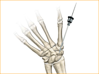
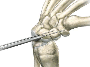
1. APPROACH AND NEEDLE INSERTION
The entry point in the proximal pole is at the tip of the scaphoid immediately adjacent to the scapholunate ligament. This can be located either using an arthroscopy or mini open dorsal approach between the third and fourth extensor compartments. Whichever approach is employed, it is essential to ensure that the guide wire does not transfix an extensor tendon.
Having established the entry point, introduce the appropriate guide wire aiming for the base of the thumb and check the position on the fluoroscope. Aim to place the leading edge of the guide wire in the subchondral surface of the distal pole of the scaphoid. Confirm the wire placement and depth under imaging.
2. FRACTURE STABILIZATION
If the fracture is unstable it may be helpful to place a second parallel guide wire using the parallel wire guides.
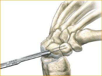
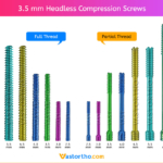
3. DETERMINE SCREW LENGTH
Measure guide wire length using either the percutaneous screw sizer, or by placing a second wire at the entry point and subtracting the difference. The screw sizer cannot be used with the arthroscopic technique due to the limited access. Subtract 4 mm from the measured length to ensure that both ends of the screw are buried within the bone.
4. ADVANCE GUIDE WIRE
Advance the guide wire through the far cortex so that it lies in the subcutaneous tissues. This minimizes the risk of accidental withdrawal of the guide wire while drilling and facilitates wire removal if it should break.
Tip: For most adult males the screw should not be longer than 26 mm, and in females 22 mm.
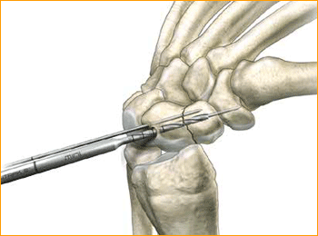
5. DRILL NEAR CORTEX
Open the near cortex with the appropriate profile drill.
6. DRILL FAR FRAGMENT
Next, drill into the far fragment with the long drill. To be effective the drill only has to advance 4–5 mm past the fracture site.
Tip: The long drill is recommended to mitigate the effects of varying bone density and distraction upon screw insertion.
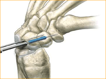
7. SCREW INSERTION
Insert the correctly sized screw with the appropriate hex driver. If resistance is met upon insertion or if distraction occurs, stop, remove the screw, redrill with the long drill, and re-insert the screw. Confirm placement and length of the screw on imaging, ensuring that both leading and trailing edges of the screw are beneath the articular surfaces. Finally remove the guide wires.