Bone Plates
Bone Screws
© Vast Ortho: Orthopedic Implants Manufacturers
First Floor, Khasra No. 104/14 | B-Block, Sant Nagar, Burari | Delhi-110084, INDIA
Herbert Screws are designed for the management of fractures where minimal tissue coverage makes standard screw use inappropriate or where extreme precision in fragment alignment is imperative. Such locations might include fractures of the:
Olecranon and malleolar region
Distal femur
Proximal tibia
Distal tibia
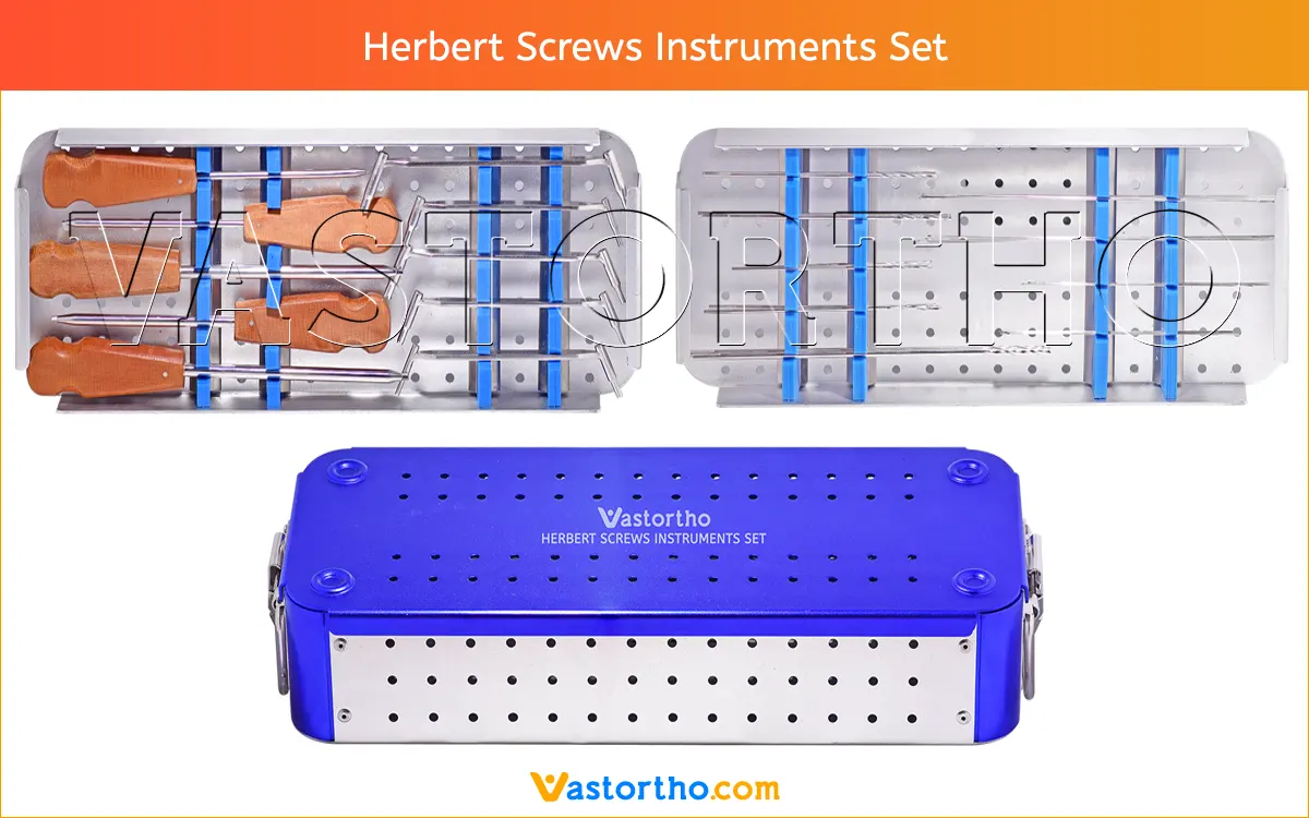
A complete instruments set are available for Herbert Screws. Instruments can be modified according to the customer’s requirement with minimum quantity required. All these instruments can be used several times.
We are keeping wide range of instruments items in this set to ensures that Doctors get almost all required items during Surgery. Below is list of items of this set.
8mm, 10mm, 12mm, 14mm, 16mm, 18mm, 20mm, 22mm, 24mm, 26mm, 28mm and 30mm.
8mm, 10mm, 12mm, 14mm, 16mm, 18mm, 20mm, 22mm, 24mm, 26mm, 28mm, 30mm, 32mm, 34mm, 36mm, 38mm, 40mm, 42mm, 44mm, 46mm, 48mm, 50mm, 55mm, 60mm, 65mm, 70mm, 75mm and 80mm.
12mm, 14mm, 16mm, 18mm, 20mm, 22mm, 24mm, 26mm, 28mm, 30mm, 32mm, 34mm, 36mm, 38mm, 40mm, 42mm, 44mm, 46mm, 48mm, 50mm, 55mm, 60mm, 65mm, 70mm, 75mm, 80mm, 85mm, 90mm, 95mm, 100mm, 105mm, 110mm, 115mm and 120mm.
STEP 1: Preparation and Insertion of Guide Wire
Select the correct guide wire and drill guide for the chosen Herbert Screws diameter. Make a stab incision and dissect a clean approach to the desired region of the bone where the compression screw will be inserted.
Properly reduce the bones intended to be repaired by the CCHS screw. Align the guide wire end of the drill guide in the direction of screw insertion. Feed the guide wire through the drill guide and advance it into the bone to the desired depth and position.
Fluoroscopy should be used to ensure correct guide wire position, alignment, and depth. If using the Tissue Protector, the Guide Wire Sleeve is inserted into the Tissue Protector to guide the guide wire. The Guide Wire Sleeve has press-fi t tabs for sleeve retention during use.
STEP 2: Herbert Screws Length Determination
Select the correct direct measuring device for the chosen screw diameter. Slide the narrow end of the direct measuring device over the guide wire and place it flush against the bone. Record the measurement at the end of the guide wire to determine the depth of the guide wire in the bone. This depth should be used to determine the length of the corresponding screw.
STEP 3: Predrilling
Select the correct drill size for the chosen Herbert Screws diameter. Align the drill end of the drill guide over the guide wire. Feed the drill through the drill guide and over the wire, and drill to the desired depth. Drill over the guide wire to the desired depth. Fluoroscopy should be used to ensure correct drill alignment and depth. Back the drill out of the bone once the desired depth has been reached without removing the guide wire.
STEP 4: Countersink
Select the correct countersink for the chosen screw diameter. Pass the countersink over the guide wire. Advance the countersink tip into the bone by applying pressure and repeatedly rotating the countersink construct clockwise to the desired depth. The black line on the countersink represents the height of the screw head.
STEP 5: Screw Insertion
Select the correct cannulated driver and handle with appropriate coupling for the chosen screw diameter. Pass the Herbert Screws over the guide wire. Using the driver, advance the screw into position. Compression is applied by rotating the driver clockwise until all distal threads have passed into the distal fragment. Compression cannot be achieved if the screw threads bridge the fracture gap.
Fluoroscopy should be used to ensure correct positioning of the screw. Advance the screw to the desired depth. The screw has a headless design that is intended to sit below the surface of the bone to minimize impingement or soft tissue irritation.
Remove the guide wire
STEP 6: Herbert Screws Removal
The Herbert Screws may be removed by using the drivers. Clear any tissue overgrowth from the screw head recess. Insert the driver and turn counterclockwise. If alignment is difficult, a guide wire may be inserted through the screw cannula to facilitate driver alignment. In this case the cannulated driver must be used.
Do you have any questions for Herbert Screws?
Please fill this form we will get in touch with you shortly.
Bone screws are the most commonly used orthopedic implants. There are many different types and sizes of screws for different types of bones. Most bone screws are made out of stainless steel or titanium alloys. The outer diameter, root diameter, and thread pitch and angle are important in determining screw mechanics.
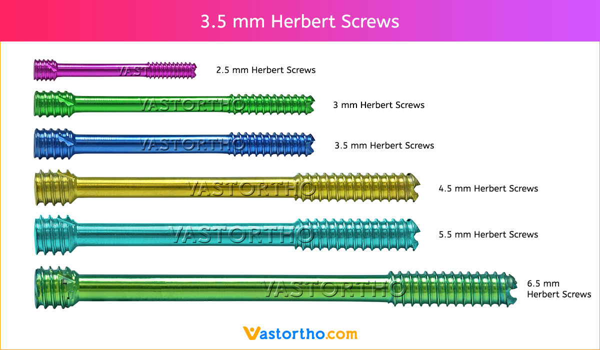
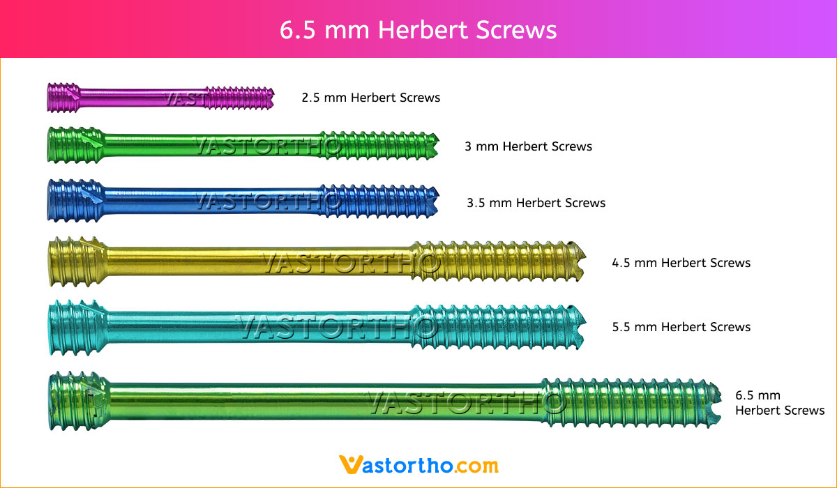
In orthopedics, screws are typically described by their outer diameter, for example, a “2.5 mm Herbert Screws” has an outside diameter of 2.5 mm. The pitch of a screw is the linear distance travelled by a screw for one full turn of the screw. The screw advances by a distance equal to the distance between the threads with each full turn. Cortical screws have a lower pitch and therefore more number of threads. Cancellous bone screws have a greater depth of the screw to increase the surface area and therefore improve the purchase, as the bone is weaker.
Screws function by converting the tightening torque into internal tension in the screw and elastic reactions in the surrounding bone. This creates compression between the fracture fragments that the screw is holding together. 2mm Cortical Screw is typically inserted into holes drilled equal to the root diameter and are either self-tapping or are inserted tapped (threaded) holes. The torque to insert cortical bone screws can be high, so the screws must be properly inserted into the correct size drilled hole and designed to withstand insertion torque levels expected in cortical bone. Cancellous bone screws have large, deep threads that grip the spongy bone well. Because of the relatively low strength of the cancellous bone, failure of the screw itself during insertion is rare, but pull out can be an issue.
Contraindications may be qualified or total, and need to be taken into consideration when evaluating the prognosis in each case. The physician’s education, training and professional judgement must be relied upon to choose the most appropriate device and treatment. Conditions presenting an increased risk of failure include:
Before using Herbert Screws, the surgeon and ancillary staff should study the safety information in these instructions, as well as any product-specific information in the product description, surgical procedures and/or brochures.
Herbert Screws is made from medical grade materials and are designed, constructed and produced with utmost care. These quality Screws assure best working results provided they are used in the proper manner. Therefore, the following instructions for use and safety recommendations must be observed.
Improper use of Screws can lead to damage to the tissue, premature wear, destruction of the instruments and injury to the operator, patients or other persons.
It is vital for the operating surgeon to take an active role in the medical management of their patients. The surgeon should thoroughly understand all aspects of the surgical procedure and instruments including their limitations. Care in appropriate selection and proper use of surgical instruments is the responsibility of the surgeon and the surgical team. Adequate surgical training should be completed before use of implants.
The following adverse effects are the most common resulting from implantation:
The operating planning is carried out following a thorough clinical evaluation of the patient, Also, x-rays must be taken to allow a clear indication of the bony anatomy and associated deformities. At the time of the operation, the corresponding implantation instruments in addition to a complete size of Herbert Screws must be available.
The clinician should discuss with the patient the possible risks and complications associated with the use of implants. It is important to determine pre-operatively whether the patient is allergic to any of the implant materials. Also, the patient needs to be informed that the performance of the device cannot be guaranteed as complications can affect the life expectancy of the device.
As with all major surgical procedures, risks, side effects and adverse events can occur. While many possible reactions may occur, some of the most common include: Problems resulting from anesthesia and patient positioning (e.g. nausea, vomiting, dental injuries, neurological impairments, etc.), thrombosis, embolism, infection, nerve and/or tooth root damage or injury of other critical structures including blood vessels, excessive bleeding, damage to soft tissues incl. swelling, abnormal scar formation, functional impairment of the musculoskeletal system, pain, discomfort or abnormal sensation due to the presence of the device, allergy or hypersensitivity reactions, side effects associated with hardware prominence, loosening, bending, or breakage of the device, mal-union, non-union or delayed union which may lead to breakage of the Herbert Screws, reoperation.