Patient Positioning and Fracture Reduction
The patient is placed in the supine position on a radiolucent fracture table and the leg is hyperflexed on the table with the aid of a leg holder, or The leg is free-draped and hung over the edge of the table.
The knee is flexed to >90°. A triangle may be used under the knee to accommodate flexion intra-operatively. It is important that the knee rest is placed under the posterior aspect of the lower thigh in order to reduce the potential of vascular compression and the risk of pushing the proximal fragment of the tibia forward. Anatomical reduction can be achieved by internal or external rotation of the fracture and by traction, adduction or abduction, and must be confirmed under image intensification. Draping must leave the knee and the distal end of the leg exposed.
Incision
Based on radiological image, a paratendenous incision is made from the patella extending down approximately 1.5–4cm in preparation of Tibial (Tibia) Nail insertion. The Patellar Tendon may be retracted laterally or split at the junction of the medial third, and lateral two-thirds of the Patellar Ligament.
Entry Point
The medullary canal is opened through a superolateral plateau entry portal. The center point of the portal is located slightly medial to the lateral tibial spine as visualized on the A/P radiograph and immediately adjacent and anterior to the anterior articular margin as visualized on the true lateral radiograph. It is located lateral to the midline of the tibia by an average of 6 percent of the tibial plateau width. Radiographic confirmation of this area is essential to prevent damage to the intra-articular structure during portal placement and Tibial (Tibia) Nail insertion.
The opening should be directed with a central orientation in relation to the medullary canal. After penetrating the cortex with the K‑Wire, the Rigid Reamer is used to access the medullary canal. Alternatively, to penetrate the cortex, the Curved Awl may be used.
Caution:
A more distal entry point may result in damage to the posterior cortex during Tibial (Tibia) Nail insertion. Guiding the Rigid Reamer over the K-Wire prior to K-Wire insertion within the Proximal Tibia will help to keep it straight while guiding the opening instrument centrally towards the canal. Do not use bent K-Wires.
Unreamed Technique
If an unreamed technique is preferred, the Smooth Tip Guide Wire is passed through the fracture site using the Guide Wire Handle. The Universal Rod with Reduction Spoon may be used as a fracture reduction tool to facilitate Guide Wire insertion, and as a “sound” to help determine the diameter of the medullary canal. The Universal Rod is 9 mm diameter. Internal rotation during insertion will aid in passing the Guide Wire down the tibial shaft. The Guide Wire should lie in the center of the metaphysis and the diaphysis in both the A/P and Lateral views to avoid offset positioning of the Tibial (Tibia) Nail. The Guide Wire handle is removed leaving the Guide Wire in place.
Reamed Technique
For reamed techniques, the Ball Tip Guide Wire is inserted through the fracture site. Except for the 8 mm Tibial (Tibia) Nail, use of the Ball Tip Guide Wire does not require a Guide Wire exchange. The Universal Rod with Reduction Spoon may be used as a fracture reduction tool to facilitate Guide Wire insertion through the fracture site.
Reaming is commenced in 0.5mm increments until cortical contact is appreciated. Final reaming should be 1mm –1.5mm larger than the diameter of the nail to be used. The Guide Wire Pusher can be used to help keep the Guide Wire in position during reamer shaft extraction. The metal cavity at the end of the handle pushed on the end of the power tool facilitates to hold the Guide Wire in place when starting to pull the power tool. When close to the Guide Wire end place the Guide Wire Pusher with its funnel tip to the end of the power tool cannulation. While removing the power tool the Guide Wire Pusher will keep the Guide Wire in place.
Tibial (Tibia) Nail Selection
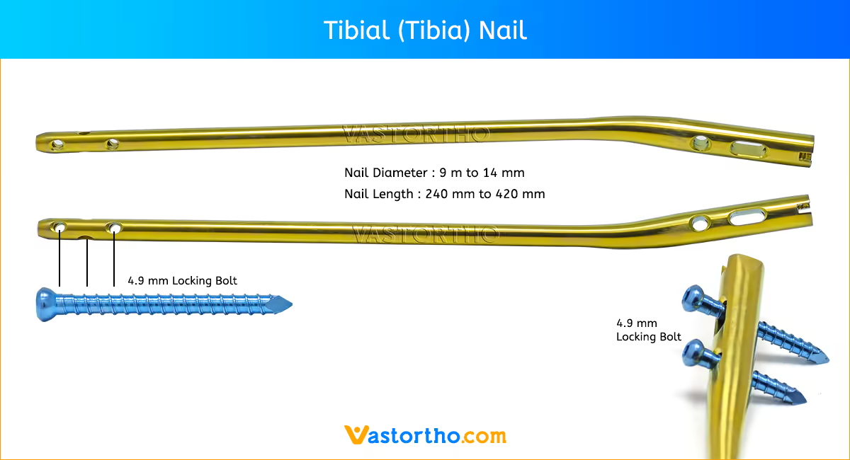
Diameter: The diameter of the selected nail should be 1–1.5mm smaller than that of the last reamer used.
Length: Tibial (Tibia) Nail length may be determined by measuring the remaining length of the Guide Wire. The Guide Wire Ruler is placed on the Guide Wire and the correct nail length is read at the end of the Guide Wire on the Guide Wire Ruler.
Nail Insertion
The selected nail is assembled onto the Tibial Target Device with the Tibial Nail Holding Screw. Securely tighten the Nail Holding Screw with the Insertion Wrench so that it does not loosen during nail insertion. To attach the Nail Handle to the Targeting Arm, turn the Quick-Lock Ring on the Targeting Arm clockwise. Triangles on the Quick-Lock Ring and the Targeting Arm indicate the correct position to attach the Nail Handle when both triangles are in line with each other.
The Nail is inserted by hand over the Ball Tip Guide Wire (if used) and into the entry site of the proximal tibia. Gently manipulate the nail to help avoid penetration of the posterior cortex. If the nail is deflected towards the posterior cortex, remove the nail, and hyperflex the knee. Under image control, use a straight reamer to ream an anterior tract in the proximal fragment. The Nail is advanced through the entry point past the fracture site to the appropriate level. Remove the Guide Wire once the nail is past the fracture site. The Slotted Hammer can be used on the Strike Plate or if dense bone is encountered, alternatively, the Universal Rod may be attached to the Strike Plate and used in conjunction with the Slotted Hammer to insert the nail.
The three circumferential grooves on the insertion post act as a guide while inserting the nail to the correct depth. When locking the Tibial (Tibia) Nail in the Static Mode, the nail is countersunk a minimum of 2mm to the chondral surface. When the implant is inserted in the Dynamic Mode, with active apposition/compression or in the Advanced Locking Mode, the recommended insertion depth is 7mm or 12mm based on how much active compression is to be applied. The final nail depth should be well below the chondral surface to minimize irritation to the Patellar Tendon.
If the nail has been inserted to far, it has to be repositioned. Repositioning of the nail should be carried out either by hand or by using the Strike Plate attached to the Target Device. The Universal Rod and Slotted Hammer may then be attached to the Strike Plate to carefully and smoothly retract the assembly. Attach the Targeting Arm to the Nail Handle by rotating the spring loaded Quick-Lock Ring on the Target Arm clockwise while connecting it to the knob on the end of the Nail Handle. A chamfer is located on the proximal end of the nail to help identify the junction of the nail and insertion post under fluoroscopy. Three circumferential grooves are located on the insertion post of the Target Device Assembly at 2mm, 7mm and 12mm from the proximal end of the nail. Depth of insertion may be visualized with the aid of fluoroscopy.
Guided Locking Mode
Before locking the nail proximally, recheck that the Nail Holding Screw is securely tightened by using the Insertion Wrench, and check that the Target Arm is properly attached to the Nail Handle. The Target Device is designed to provide four options for proximal locking when using the Standard Tibial Nail. In Static Locking Mode all three indicated holes may be used. The dynamic hole is used to lock the nail in the controlled Dynamization or Apposition/Compression Modes. Both the dynamic and more proximal of the two oblique locking holes are used in the Advanced Locking Mode. Proper placement of the Advanced Compression Screw against the transverse Partially Threaded Locking Screw (Shaft Screw) will block the more distal of the two oblique locking holes even if fully compressed.
The Long Tissue Protection Sleeve together with the Long Drill Sleeve and the Long Trocar is inserted into the Target Device by pressing the safety clip. The mechanism will keep the sleeve in place and prevent it from falling out. It will also prevent the sleeve from sliding during screw measurement. To release the Tissue Protection Sleeve, the safety clip must be pressed again and held while removing the sleeve.
Static Locking Mode
For static locking of the Standard Tibia Nail, both proximal oblique screws and the M/L Locking Screw may be used. In highly unstable, comminuted fractures the M/L screw is placed in the static position of the oblong hole. This may further improve stability of the proximal fragment. If secondary dynamization is planned, the M/L screw may be inserted in the dynamic position of the oblong hole on the Target Device. This allows controlled dynamization of the fracture in cases of delayed union after removal of the proximal oblique screws.
Always start with the most distal oblique Fully Threaded Locking Screw. The Long Tissue Protection Sleeve (assembled with the Long Drill Sleeve and Trocar) is positoned through the static locking hole on the Target Device. A small skin incision is made, and while pressing the safety clip, the Tissue Protection Sleeve is pushed through until it is in contact with the anterior cortex. The Long Trocar is removed, with the Tissue Protection Sleeve and Drill Sleeve remaining in position.
For accurate drilling and easy determination of screw length, use the center-tipped, Drill. The centered Drill is forwarded through the Drill Sleeve and pushed onto the cortex. After drilling both cortices, the screw length may be read directly off of the calibrated Drill at the end of the Drill Sleeve. If measurement with the Screw Gauge, Long is preferred, first remove the Drill Sleeve, Long and read the screw length directly at the end of the Tissue Protection Sleeve, Long.
The position of the end of the Drill as it relates to the far cortex is equal to where the end of the screw will be. Therefore, if the end of the Drill is 3 mm beyond the far cortex, the end of the screw will also be 3 mm beyond. The Screw Gauge, Long, is calibrated so that with the bend at the end pulled back flush with the far cortex, the screw tip will end 3 mm beyond the far cortex. Alternatively, stop the drill when it engages the far cortex and measure the drill bit depth off of the calibrated drill. Add 5 mm to this length to obtain the correct screw length. When the Drill Sleeve is removed, the correct Locking Screw is inserted through the Tissue Protection Sleeve using the Long Screwdriver Shaft with the Teardrop Handle.
Alternatively, the 3.5 mm Hex Self-Holding Screwdriver can be used for the screw insertion. The screw is advanced through both cortices. The screw is near its’ proper seating position when the groove around the shaft of the screwdriver is approaching the end of the Tissue Protection Sleeve. Repeat the locking procedure for the more proximal oblique Locking Screw.
Freehand Distal Locking
The freehand technique is used to insert Locking Screws into both the M/L and A/P holes in the nail. Rotational alignment must be checked prior to locking the nail statically. Multiple locking techniques and radiolucent drill devices are available
for freehand locking. The critical step with any freehand locking technique is to visualize a perfectly round locking hole with the C-Arm. The center-tipped Drill is held at an oblique angle pointing to the center of the locking hole. Upon X-Ray verification, the Drill is placed perpendicular to the nail and drilled through the medial cortex. Confirm in both the A/P and M/L planes by X-Ray that the drill passes through the hole in the nail.
The Screw Gauge, Long can be used to determine the screw length. As detailed in the proximal locking section, the position of the end of the drill is equal to the end of the screw as they relate to the far cortex. Routine Locking Screw insertion is employed with the assembled Screwdriver Shaft and Teardrop Handle. Alternatively, the 3.5mm Hex Self-Holding Screwdriver can be used for the screw insertion.
End Cap Insertion
After removal of the Target Device, an End Cap is used. Different sizes of End Caps are available to adjust nail length and to reduce the potential for bony ingrowth into the proximal threads of the Tibial (Tibia) Nail. The End Cap is inserted with the Screwdriver Shaft and Teardrop Handle after intra-operative radiographs show satisfactory reduction and hardware implantation. Fully seat the End Cap to minimize the potential for loosening. Thoroughly irrigate the wound to prevent debris from remaining within the knee joint. Close the wound using standard technique.
Dynamic Locking Mode
When the fracture profile permits, dynamic locking may be utilized for transverse, axially stable fractures. Controlled dynamization is performed by statically locking the nail distally with at least two screws in a freehand technique. In the Dynamic Locking Mode of the Standard Tibial Nail, the Partially Threaded Locking Screw (Shaft Screw) is placed in the dynamic position of the M/L oblong hole. The two oblique proximal screws are not inserted. This allows the nail to move relative to the partially Threaded Locking Screw (Shaft Screw) and the fracture to settle while maintaining torsional stability.
Apposition/ Compression Locking Mode
In transverse or axially stable fracture patterns, active apposition/compression increases fracture stability, may enhance fracture healing and allow for early weight bearing. Tibia Nail provide the option to treat a tibial fracture with active mechanical apposition/compression prior to leaving the operating room. If active apposition/compression is required for the Tibia Nail, a Partially Threaded Locking Screw is inserted via the Target Device in the dynamic position of the of the oblong hole. The Distal Tibial Nail uses the static position of the oblong hole. This will allow for a maximum of 7mm of active, controlled apposition/compression using the Advanced Compression Screw. In order to insert the Partially Threaded Locking Screw (Shaft Screw), drill both cortices with the Drill. Correct screw length may be read from the calibration on the Drill at the end of the Drill Sleeve. The near cortex ONLY is overdrilled using the Drill.
Another alternative is that after the Partially Threaded Locking Screw (Shaft Screw) is inserted, the Nail Holding Screw securing the nail to the insertion post is removed, leaving the insertion post intact with the Tibial (Tibia) Nail. This will act as a guide for the Compression Screw. The Compression Screw is inserted with the Compression Screwdriver Shaft assembled on the Teardrop Handle through the insertion post. When the Compression Screwdriver Shaft is close to the Target Device, it indicates the engagement of the apposition/compression feature of the nail. The Long Tissue Protection Sleeve is removed and the Compression Screw is gently tightened utilizing the twofinger technique. As the Compression Screw is advanced against the 5.0mm Partially Threaded Locking Screw (Shaft Screw), it draws the distal fracture segment towards the fracture site, employing active apposition/compression. Image intensification will enable the surgeon to visualize active apposition/compression. Some bending of the Partially Threaded Locking Screw may be seen.
Advanced Locking Mode
In order to achieve additional fixation, and to reduce the load on the Partially Threaded Locking Screw, the design of the Tibia Nail provide the opportunity to insert an additional Fully Threaded Locking Screw (Shaft Screw) into the more proximal of the two oblique holes after the optimum amount of apposition/compression is attained. Affix the Compression Screw onto the self-retaining Compression Screwdriver Shaft. Remove the Nail Holding Screw leaving the Target Device in place. Advance the Compression Screw through the Target Device until the ring marked on the Compression Screwdriver Shaft is close to the Target Device and compression is applied. To insert the Advanced Compression Screw, follow the procedure.
To reattach the Target Device, detach the Teardrop Handle from the Compression Screwdriver Shaft and screw the Nail Holding Screw over the Compression Screwdriver Shaft back into position. Prior to guided locking via the Target Device, the Nail Holding Screw must be securely tightened with the Insertion Wrench. To insert the proximal oblique Fully Threaded Locking Screw, follow the locking procedure for static locking.
Tibial (Tibia) Nail Removal
Tibial (Tibia) Nail removal is an elective procedure. If needed, the End Cap and Advanced Compression Screw are removed with the Screwdriver Shaft and Teardrop Handle. If the Advanced Locking Mode was utilized, first remove the End Cap, then the most proximal screw, then the Advanced Compression Screw can be removed.
The Universal Rod is inserted into the driving end of the nail. All Locking Screws are removed with the Long Screwdriver Shaft and Teardrop Handle. Alternatively, the 3.5mm Hex Self-Holding Screwdriver can be used for the screw removal. The Slotted Hammer or optional Sliding Hammer is used to extract the nail in a controlled manner. Close the wound in the usual manner.