Position patient
Place the patient in a supine position on the operating table.
Reduce fracture
If possible reduce the fracture while closed under the image intensifier. If an operating table without extension is used, reduce the fracture by flexion, lengthwise traction, abduction and internal rotation. Fix the fracture temporarily with Kirschner wires. Position the Kirschner wires so that they do not hamper insertion of the screw and Locking Dynamic Hip Screw plate.
Access
The proximal femur is approached laterally. Make a 15–20 cm straight incision starting two fingerwidths proximal to the greater trochanter. Split the iliotibial tract lengthwise. Detach the M. vastus lateralis dorsally from the intermuscular membrane, retract ventrally and, if necessary, make a slight notch in the muscle in the region of the innominate tubercle. Expose the proximal femoral shaft without retracting the periosteum.
Determine antetorsion
To determine the antetorsion of the femoral neck using the Angled Guide and the T-Handle , place a Kirschner wire ventrally over the femoral neck and tap the tip slightly into the femoral head.
Determine entry point for the screw and insert guide wire
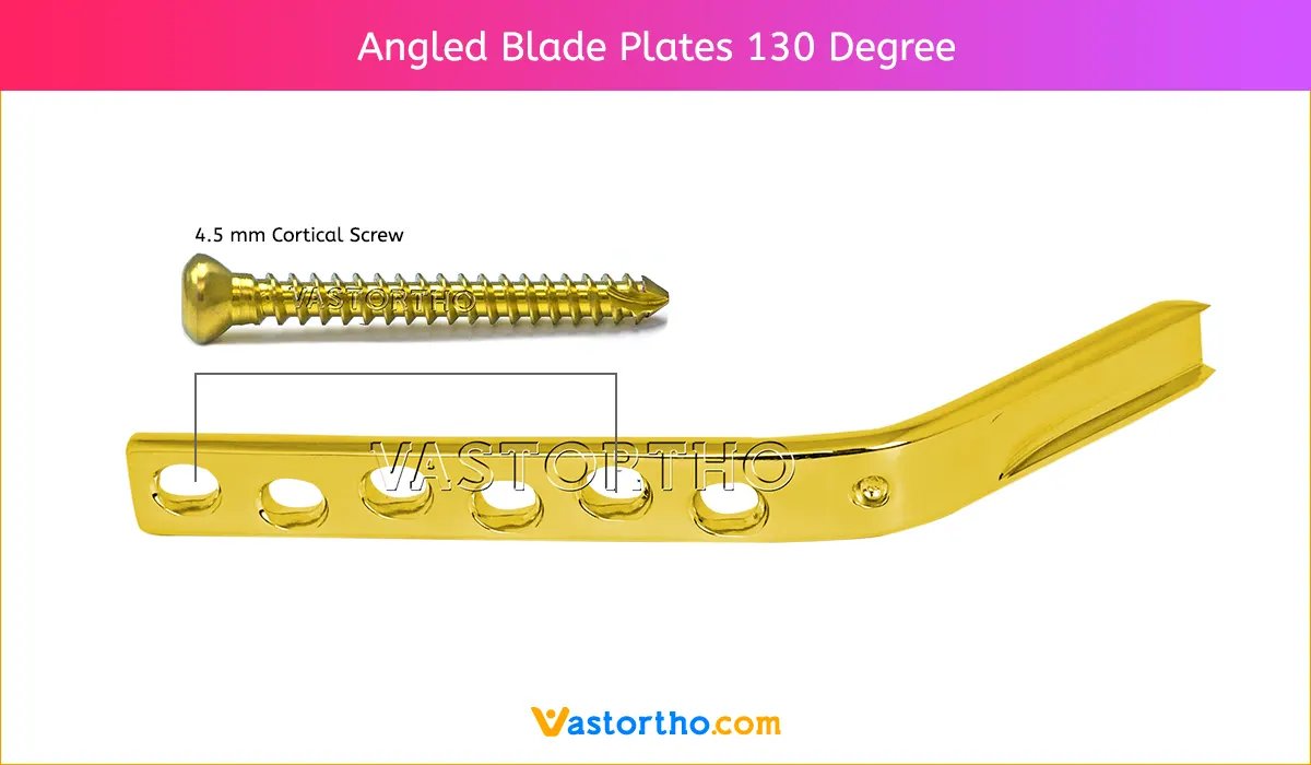
Implants with CCD angles from 130° to 150° are available. Depending on the angle of the implant, the entry point for the screw is approx. 2.5 – 6.0 cm distal to the innominate tubercle.
Locate the angled guide and drill the outer cortex using the Drill Bit 2.0 mm. Insert the Guide Wire with Threaded Tip 2.5 mm until the tip reaches the subchondral part of the femur head.
The guide wire runs approximately 6 mm proximal to Adams’ arc in the dorsocaudal quadrant of the femoral head. The thread on the tip of the guide wire stops the wire from being pulled out. Check the position of the guide wire under the image intensifier in the a.p. view and the Lauenstein position. If an extension table is used, record an axial view.
Note: Leave the guide wire in the femur until the plate is fitted. If the guide wire is not correctly positioned it must be reinserted. Once the screw is inserted in an incorrect position, no subsequent correction is possible.
Measure the length of the guide wire
Slide the Direct Measuring Device over the guide wire and measure the length of the guide wire in the bone. Remove the antetorsion Kirschner wire.
Reaming
Assemble the triple reamer: Slide the Reamer over the Drill Bit 8.0 mm until it clicks into place at the selected mark. The reaming depth can be adjusted in 5 mm increments. Secure the reamer by tightening the Knurled Nut. Adjust the reaming depth on the Triple Reamer. The appropriate reaming depth is 10 mm less than the measured length of the guide wire. Ream the screw channel until the tip of the reamer is 10 mm in the subchondral part of the femoral head. The length of the appropriate screw is identical to the reaming depth.
Notes: While reaming, ensure that the guide wire does not bend. Bending the guide wire can result in incorrect placement of the Locking Dynamic Hip Screw plate and screw. If the guide wire is pulled out during reaming it must be replaced. Push the short Centering Sleeve into the drill hole and insert a screw with the shaft foremost into the centering sleeve. The guide wire can now easily be reinserted back in its original position. Remove the triple reamer.
Insert the Lag screw
Slide the insertion instruments over the guide wire and advance the long Centering Sleeve into the drilled hole. Insert the screw until the zero mark reaches the lateral cortex. Continue inserting the screw for a further 5 mm if the bone is osteoporotic. The handle of the Wrench must remain parallel to the femoral axis since only in this screw position can the plate be positioned correctly over the flat-sided shaft of the screw against the femoral shaft.
Position Locking Dynamic Hip Screw plate
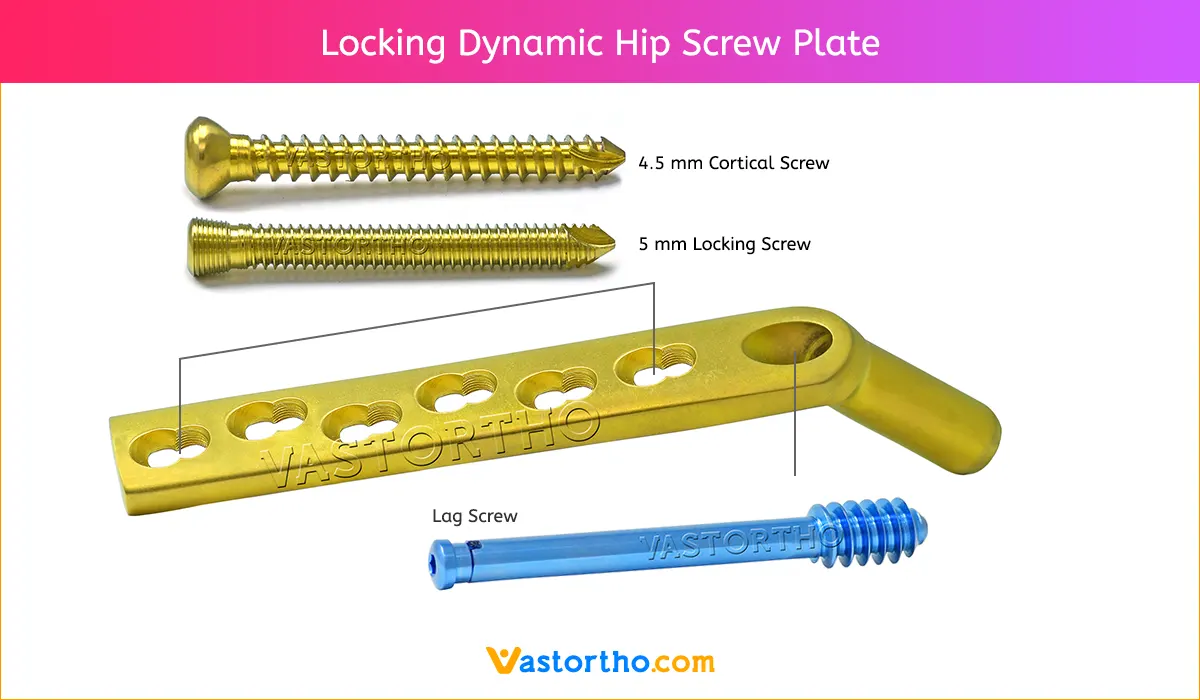
Position the plate over the short Connecting Screw against the femoral shaft. Loosen the connecting screw and remove the Guide Shaft. Set the power tool to reverse operation to remove the guide wire. Dispose of the guide wire.
Tap Locking Dynamic Hip Screw Plate
Tap the plate into the predrilled channel using the Impactor. Compress the fracture by gentle hammer taps against the impactor.
Fix Locking Dynamic Hip Screw Plate
Using the Drill Guide 4.5 and the Drill Bit 3.2 mm, drill neutral holes through the plate holes. Fix the plate using cortex screws 4.5 mm of the appropriate length.
Option
The fracture fragments can also be compressed with the Compression Screw. First fix the plate to the femoral shaft with screws. Insert and tighten the compression screw. Particularly if the bone is osteoporotic, insert the compression screw carefully and ensure that the thread is not stripped. The compression screw can then be removed.
Insert locking device (Option)
The Locking Device is used to temporarily block the sliding mechanism. In order to fully countersink the locking device in the Locking Dynamic Hip Screw plate barrel, the selected screw must be 10 mm shorter than the reaming depth. The screw must then be inserted 10 mm deeper, on the wrench reaches the lateral cortex. Tighten and secure the locking device using the Torque-indicating Screwdriver. To ensure that an optimal locking force is achieved, the locking device must be tightened to a torque.
Position trochanter stabilizing plate on Locking Dynamic Hip Screw Plate
Insert the screw and plate. If an anti-rotation screw is to be used, the screw must be inserted in a slightly more caudal direction than for the standard technique. Fix the plate by inserting a cortex screw 4.5 mm through the second proximal plate hole and insert a new guide wire. Locate the Trochanter stabilizing plate flush against the plate.
Fix plates
Fix the Trochanter stabilizing plate and the Locking Dynamic Hip Screw plate using cortex screws 4.5 mm of the appropriate length. Depending on the indication, individual fracture fragments of the greater trochanter can be fixed against the scooped section of the Trochanter stabilizing plate using screws 4.0 mm or cerclage wires.
Insert anti-rotation screw (option)
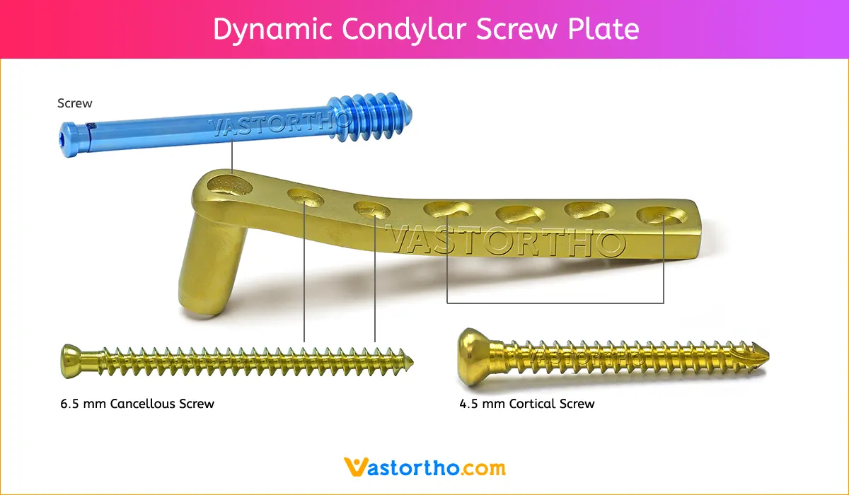
An anti-rotation screw can be inserted cranially and parallel to the screw. Cancellous bone screws 6.5 mm, cannulated screws 7.0 mm and cannulated screws 7.3 mm can be used. Position the Parallel Drill Guide over the guide wire. Insert the appropriate drill sleeve system in the 12 mark of the guide. For the cancellous bone screws 6.5 mm tap a threaded hole. For cannulated screws 7.0 mm and 7.3 mm, insert a guide wire. Insert the screw according to the usual insertion technique. Remove the guide wire.


