1. Position patient
Place the patient in a supine position on a normal radiolucent operating table such that the knee can be flexed through 90°.
2. Access
Access is via a 15–20 cm incision along the connecting line between the greater trochanter, the lateral femoral condyle and the tibial tuberosity.
3. Reduce articular fracture component
Temporary fixation with Kirschner wires, which are subsequently replaced by lag screws. The position of these screws must not hamper the insertion of the screw.
Determine entry point for the screw and insert guide wire
The entry point for the screw is on the femoral shaft axis approx. 2 cm from the knee joint. Using two Kirschner wires determine the correct alignment of the screw.
– The first Kirschner wire in the frontal plane marks the orientation of the knee joint cavity at the level of the condyles.
– Insert the second Kirschner wire ventrally over the lateral and medial condyles to demonstrate the incline of the femoropatellar joint surface.
– Insert the Guide Wire 2.5 mm at the predetermined entry point such that it runs parallel both to the first Kirschner wire in a.p. view and to the second, ventrally located wire in the axial view. Insert the guide wire until the medial cortex is reached.
4. Remove the Kirschner wires.
Determine entry point in the proximal femur Using the Condylar Plate Guide, determine the correct alignment of the guide wire. The entry point is located at the transition from the ventral third to the mid-third of the greater trochanter, since the guide wire in the femoral neck – in relation to the Lauenstein projection – must be inserted in the centre. Determine the 95° alignment to the axis of the femoral shaft using the Angled Guide or the Condylar Plate Guide.
5. Measure the length of the guide wire
Slide the Direct Measuring Device over the guide wire and determine the length.
6. Reaming
Adjust the reaming depth on the Triple Reamer. The appropriate reaming depth is 10 mm shorter than the measured length of the guide wire. Assemble the triple reamer: Slide the Reamer over the Drill Bit 8.0 mm until it clicks into place at the selected mark. Secure the reamer by tightening the Knurled Nut. Ream down to the stop. The appropriate screw is 5 mm shorter than the reaming depth. Remove the triple reamer.
Option: If the bone is hard, tap the thread using the Tap and the short Centering Sleeve. Tap the thread until the selected depth in the small window of the centering sleeve reaches the lateral cortex.
7. Insert the screw
Slide the insertion instruments over the guide wire and advance the long Centering Sleeve into the drilled hole. Insert the screw until the 5 mm mark reaches the lateral cortex. In case of osteoporotic bone continue inserting the screw for a further 5 mm. The handle of the wrench must remain parallel to the femoral axis since only in this screw position can the Locking Dynamic Condylar Screw plate be positioned correctly over the flat-sided shaft of the screw against the femoral shaft.
Note: Do not use the wrench to reduce the fracture as this only allows limited transmission of forces. Remove the wrench and long centering sleeve.
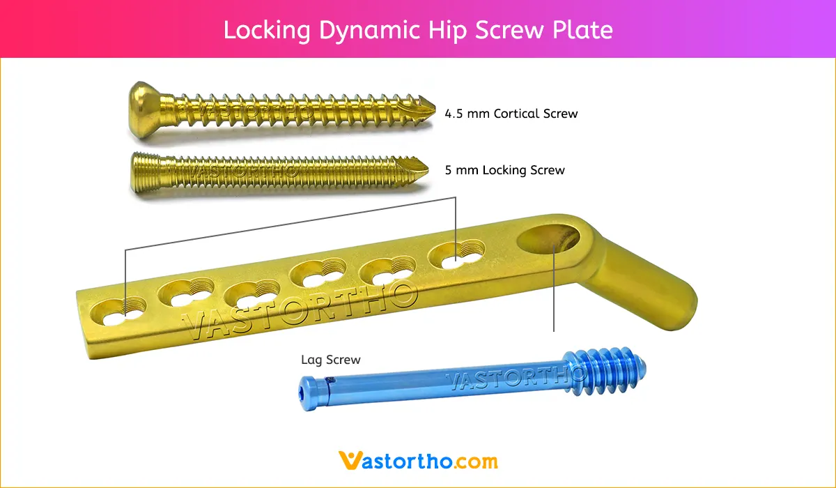
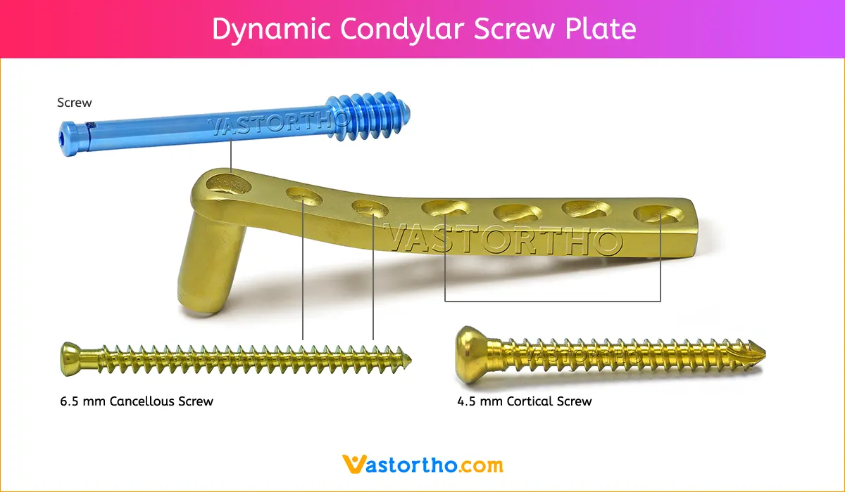
8. Position Locking Dynamic Condylar Screw plate
Position the Locking Dynamic Condylar Screw Plate over the connecting screw against the femoral shaft. Loosen the connecting screw and remove the Guide Shaft. Set the drill to reverse operation to remove the guide wire. Dispose of the guide wire.
9. Tap the plate
Tap the plate into the predrilled channel using the Impactor. Compress the fracture by gentle hammer taps against the impactor.
10. Achieve compression using cancellous bone screws 6.5 mm
Secure the two joint fragments of the Y-fracture by interfragmental fixation using two cancellous bone screws 6.5 mm through the two distal plate holes (use the Drill Guide 4.5, the Drill Bit 3.2 mm and the Tap according to the standard technique).
11. Insert compression screw
In Y-fractures, compression must be achieved using the Compression Screw. First fix the plate to the femoral shaft with screws. Insert and tighten the compression screw. Particularly if the bone is osteoporotic, insert the compression screw carefully and ensure that the screw thread is not stripped.
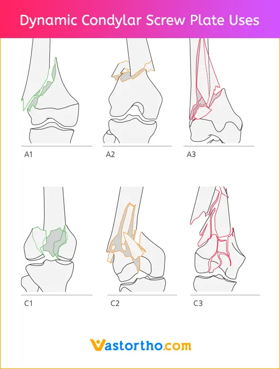
12. Reduce metaphyseal fracture component
Reducing the shaft fragment against the plate can achieve an anatomically correct reduction in respect of varus/valgus deviations. The length and rotation must be adapted by comparing the contralateral side.
13. Fix Locking Dynamic Condylar Screw plate
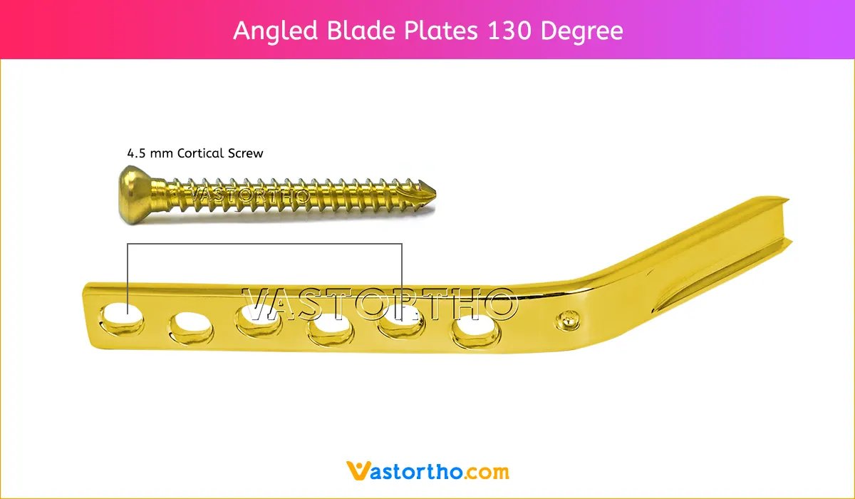
Using the Drill Guide 4.5 and the Drill Bit 3.2 mm, drill neutral holes through the plate holes. Fix the plate using cortex screws 4.5 mm of the appropriate length.
Note: With simple fractures, before fixing the plate, axial compression can be generated between the distal joint block and the shaft fragment using the Tension Device.
Insert the short Connecting Screw in the Guide Shaft and screw into the inner thread of the screw. The cam and slot must interlock correctly and firmly. Slide the long Centering Sleeve over the Wrench. Insert the whole assembly into the wrench.


